Guide Chain Sprocket: A Comprehensive Guide
Guide chain sprockets are essential components in power transmission systems, facilitating efficient motion transfer across diverse mechanical applications.
These robust elements, often utilized with roller chains, ensure reliable performance and longevity within industrial and manufacturing settings.
Guide chain sprockets represent a fundamental element within mechanical power transmission, serving as the crucial interface between rotating power and linear motion. Historically, chain drives have excelled in handling substantial loads, even within challenging operational environments, and continue to do so today.
These sprockets aren’t merely toothed wheels; they are precisely engineered components designed to mesh seamlessly with chains, converting rotational movement into precise, controlled linear movement. Understanding their function is paramount for engineers and technicians involved in designing, maintaining, and repairing machinery. The effectiveness of a chain drive system hinges significantly on the quality and correct specification of its sprockets.
From simple conveyor systems to complex industrial machinery, guide chain sprockets play a vital role. Their design considerations encompass factors like chain pitch, tooth profile, material strength, and operational load, all contributing to optimal performance and extended service life.
What is a Guide Chain Sprocket?
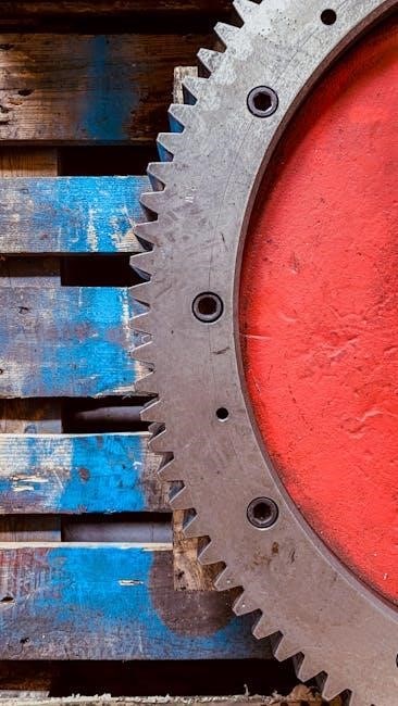
A guide chain sprocket is a profiled wheel with teeth designed to engage with the links of a chain, transmitting rotational motion. Essentially, it’s a component that ‘guides’ the chain, ensuring smooth and efficient power transfer. Unlike gears which operate through direct tooth-to-tooth contact, sprockets rely on the chain wrapping around their circumference.
These sprockets come in various configurations – single-strand, double-strand, or even multiple-strand – to accommodate different chain types and load requirements. The pitch diameter, representing the distance from the center of the sprocket to the chain’s pitch line, is a critical parameter. It directly influences the gear ratio when paired with another sprocket.
The ratio of pitch diameters between sprockets determines the gear ratio, though calculating this using tooth counts is far simpler. A sprocket’s tooth geometry is carefully designed to minimize wear and maximize chain engagement, ensuring reliable performance and longevity within the system.
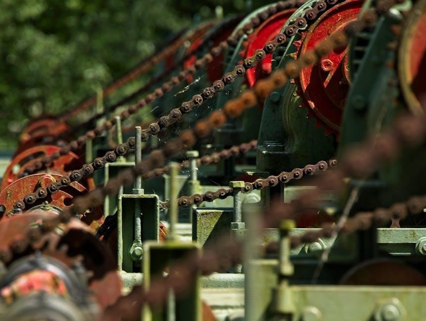
The Role of Sprockets in Chain Drives
In chain drives, sprockets serve as the crucial interface between rotating power and linear or rotational output. They convert the rotational motion of a motor or engine into the linear motion of a chain, or vice versa, enabling power transmission across distances. Unlike geared systems with direct meshing, sprockets utilize the chain as a flexible connector.
Sprockets effectively transmit torque, and their size (tooth count) directly impacts the speed and mechanical advantage of the drive. Larger sprockets yield higher speeds with reduced torque, while smaller sprockets provide increased torque but lower speeds. This allows for versatile design options.
Chain drives, utilizing sprockets, excel in handling heavy loads and operating in harsh conditions, maintaining their relevance despite advancements in other transmission technologies. They offer a robust and reliable solution for numerous industrial and mechanical applications, proving their enduring value.

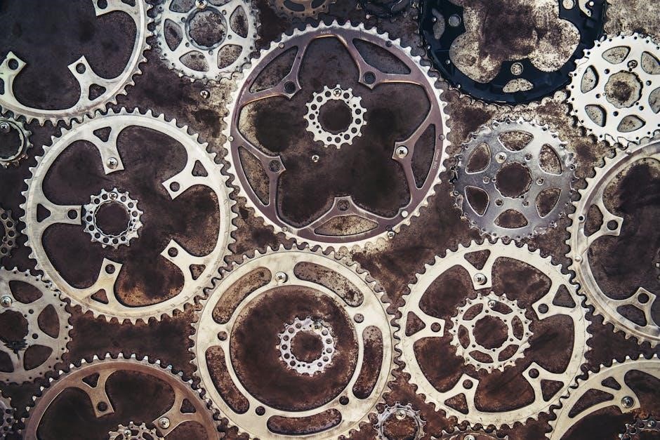
Types of Guide Chain Sprockets
Guide chain sprockets come in diverse configurations, including ANSI roller chain, single-strand, double-strand, and multiple-strand options, alongside European standard designs, catering to varied application needs.
ANSI Roller Chain Sprockets
ANSI roller chain sprockets represent a widely adopted standard in power transmission, particularly prevalent in North American industries. These sprockets are characterized by a clear mathematical theme and relatively simple design, making them accessible and cost-effective for numerous applications. However, it’s important to note that ANSI sprockets generally exhibit a shorter lifespan compared to their European counterparts, primarily due to their smaller tooth pitches.
The ANSI standard encompasses a broad range of sprocket configurations, specifically covering eight distinct strand types. These include single-strand, double-strand, triple-strand, and multiple-strand options extending up to ten strands (4, 5, 6, 8, and 10). This variety allows for flexibility in handling different power transmission requirements and load capacities. The selection of the appropriate strand type depends on the specific torque and speed demands of the driven system, ensuring optimal performance and durability.
Single-Strand Sprockets
Single-strand sprockets represent the most basic and commonly utilized type within the ANSI roller chain sprocket family. These sprockets are designed for applications requiring lower torque transmission capabilities, making them ideal for lighter-duty machinery and simpler drive systems. Their straightforward construction contributes to their cost-effectiveness and ease of maintenance, further enhancing their appeal for a wide range of industrial and commercial uses.
Typically employed with single-strand roller chains, these sprockets feature a single row of teeth engaging with the chain’s rollers. This configuration is suitable for applications where shock loading and high tensile forces are not significant concerns. While offering a simpler solution, single-strand sprockets are often chosen for their efficiency and reliability in less demanding environments. They form the foundation for many power transmission systems, providing a dependable and economical solution for various mechanical needs.
Double-Strand Sprockets
Double-strand sprockets are engineered to handle significantly increased torque loads compared to their single-strand counterparts. Featuring two parallel rows of teeth, these sprockets engage with double-strand roller chains, effectively doubling the chain’s tensile strength and power transmission capacity. This makes them well-suited for applications demanding higher performance and reliability, such as heavier machinery and more robust drive systems.
The increased tooth count and wider profile of double-strand sprockets contribute to their enhanced load-bearing capabilities. They are commonly found in applications where shock loading and fluctuating power demands are prevalent. While slightly more complex and potentially more expensive than single-strand options, the added durability and performance benefits often justify the investment. They provide a robust solution for demanding mechanical applications, ensuring efficient and dependable power transfer.
Triple-Strand and Multiple-Strand Sprockets
Triple-strand and multiple-strand sprockets represent the pinnacle of power transmission capability within the ANSI roller chain family. Designed for extremely high torque and load applications, these sprockets utilize three or more parallel rows of teeth to engage with correspondingly multi-strand chains. Configurations extend up to eight strands (and beyond in specialized cases), providing exponential increases in tensile strength and power handling capacity.
These robust components are crucial in heavy-duty machinery, industrial equipment, and applications where failure is not an option. While demanding precise alignment and robust mounting, the benefits of increased reliability and power transfer are substantial. They are often employed in scenarios involving significant shock loads, continuous high-power output, or critical operational requirements. Selecting the appropriate strand count is vital for optimizing performance and ensuring long-term system integrity.
European Standard Sprockets

European standard sprockets, differing from their ANSI counterparts, generally exhibit enhanced durability and a longer operational lifespan. This increased longevity stems from larger tooth pitches and refined manufacturing processes, contributing to reduced wear and tear under demanding conditions. While ANSI sprockets prioritize a straightforward mathematical design, European standards emphasize robustness and extended service intervals.
These sprockets are frequently favored in applications requiring minimal maintenance and prolonged reliability, despite potentially higher initial costs. They are designed to withstand substantial stress and offer superior performance in harsh environments. The design philosophy prioritizes a more gradual wear pattern, extending the overall component life. Selecting European standard sprockets often represents a strategic investment in long-term operational efficiency and reduced downtime.

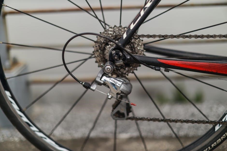
Chain Types Compatible with Sprockets
Various chain types, including roller, silent, leaf, and specialized chains, seamlessly integrate with guide chain sprockets, offering diverse solutions for power transmission and mechanical functionality.
Roller Chains
Roller chains represent a prevalent choice for power transmission systems utilizing guide chain sprockets, celebrated for their efficiency, durability, and ability to handle substantial loads. These chains consist of a series of interconnected rollers, pins, and plates, enabling smooth engagement with sprocket teeth.
The rollers minimize friction during operation, contributing to reduced wear and enhanced performance. Roller chains are exceptionally versatile, finding applications across a broad spectrum of industries, including manufacturing, agriculture, and transportation. They are available in various pitches and strand configurations – single, double, triple, and multiple – to accommodate diverse power requirements and operating conditions.
Selecting the appropriate roller chain necessitates careful consideration of factors like tensile strength, pitch, and operating environment. Regular lubrication is crucial for maximizing chain lifespan and maintaining optimal efficiency. Their widespread availability and cost-effectiveness further solidify roller chains as a cornerstone of mechanical power transmission.
Silent Chains
Silent chains offer a distinct alternative to traditional roller chains when paired with guide chain sprockets, particularly in applications demanding quiet operation. Unlike roller chains, silent chains utilize specialized plate designs that engage with the sprocket teeth without the characteristic clicking sound. This makes them ideal for environments where noise reduction is paramount, such as in precision machinery or office equipment.

Constructed from solid, riveted plates, silent chains exhibit excellent stability and resistance to stretching. While generally possessing a lower load capacity compared to roller chains of equivalent size, they excel in applications requiring precise timing and smooth, vibration-free power transmission.
They are frequently employed in automotive timing systems and industrial machinery where minimizing noise pollution is critical. Proper alignment and lubrication are essential for ensuring the longevity and optimal performance of silent chains, maximizing their benefits in demanding operational scenarios.
Leaf Chains
Leaf chains represent a specialized category of chains designed for applications involving intermittent motion, high tensile strength, and lifting operations when used with guide chain sprockets. Distinguished by their unique construction – consisting of multiple plate links resembling leaves – these chains offer exceptional flexibility and resistance to elongation. They are particularly well-suited for vertical lifting mechanisms, such as those found in forklifts, hoists, and elevators.
Unlike roller chains, leaf chains do not utilize rollers, relying instead on the direct contact between the chain plates and the sprocket teeth for power transmission. This design contributes to their high load-carrying capacity and ability to withstand shock loads.
Proper lubrication is crucial for minimizing wear and ensuring smooth operation. Leaf chains are often preferred in environments where precise positioning and reliable lifting performance are essential, offering a robust solution for demanding industrial applications.
Specialized Chains
Specialized chains encompass a diverse range of chain types engineered for unique applications beyond the scope of standard roller, silent, or leaf chains when paired with guide chain sprockets. These chains often feature modified link geometries, specialized materials, or unique coatings to address specific operational demands. Examples include engineering chains designed for high-precision indexing, plastic chains for corrosion resistance in food processing, and hollow pin chains facilitating lubrication directly to the pin and bush.
These chains are frequently employed in industries requiring tailored solutions, such as robotics, automation, and specialized manufacturing processes. Their design prioritizes specific performance characteristics like increased wear resistance, reduced noise, or enhanced chemical compatibility.
Selecting the appropriate specialized chain necessitates a thorough understanding of the application’s requirements, ensuring optimal performance and longevity within the overall system.
Understanding Sprocket Specifications
Sprocket specifications, including pitch, tooth count, and material, are crucial for optimal chain drive performance. Accurate specification ensures efficient power transmission and system reliability.
Chain Pitch Explained
Chain pitch is a fundamental specification defining the distance between the centers of adjacent pins in a chain, typically measured in inches. It directly correlates to the sprocket’s tooth geometry and influences the overall performance of the power transmission system. A larger pitch equates to larger teeth, capable of handling greater loads but operating at lower speeds.
Commonly encountered pitches include 0.25, often referred to as a 25 chain, and 0.375, known as a 35 chain. These values represent the pitch diameter in inches per tooth. The REV Robotics building system frequently utilizes the 25 chain due to its balance of size and strength. Understanding pitch is vital for ensuring compatibility between the chain and sprocket, preventing premature wear, and maximizing efficiency. Selecting the correct pitch is paramount for a durable and effective mechanical linkage.
0.25 Pitch (25 Chain)
The 0.25 pitch chain, commonly known as a 25 chain, represents a widely utilized standard in power transmission applications, particularly where space is limited or moderate loads are involved. This chain features a pitch of 0.25 inches, meaning the distance between the centers of consecutive pins measures a quarter of an inch.
REV Robotics prominently features the 25 chain within its building system, highlighting its suitability for robotics and automation projects. Its smaller size allows for compact designs, while still providing adequate strength for many tasks. Sprockets designed for a 25 chain will have teeth spaced to precisely match this 0.25-inch pitch. Proper engagement between the chain and sprocket teeth is crucial for efficient power transfer and minimizing wear. Selecting a 25 chain requires careful consideration of the application’s torque and speed requirements.
0.375 Pitch (35 Chain)
The 0.375 pitch chain, frequently referred to as a 35 chain, offers increased strength and durability compared to its 0.25 (25) pitch counterpart. With a pitch of 0.375 inches, meaning the distance between pins is just over three-eighths of an inch, this chain is well-suited for applications demanding higher torque capacity and greater resistance to wear.
Like the 25 chain, the 35 chain is a common standard, though it occupies a space between lighter-duty and heavy-duty applications. Sprockets designed for a 35 chain will have correspondingly larger teeth to ensure proper meshing and efficient power transmission. Choosing a 35 chain involves evaluating the load requirements, operating speed, and environmental conditions. Its robust construction makes it a reliable choice for various industrial and mechanical systems where longevity and performance are paramount.
Sprocket Tooth Count and Gear Ratio
The relationship between sprocket tooth count and gear ratio is fundamental to understanding chain drive systems. A gear ratio is determined by dividing the number of teeth on the driven sprocket by the number of teeth on the driving sprocket. Alternatively, and more commonly, the ratio is calculated directly from the number of teeth, simplifying the process.
A larger driven sprocket relative to the driving sprocket results in a gear reduction, increasing torque but decreasing speed. Conversely, a smaller driven sprocket yields a gear increase, boosting speed at the expense of torque. Precise tooth counts are crucial for achieving the desired mechanical advantage. The pitch diameter, while relevant, is less frequently used for ratio calculations due to the simplicity of tooth-based determination. Careful selection ensures optimal performance and efficiency within the system.

Sprocket Material and Durability
Sprocket durability hinges on material selection, with ANSI sprockets generally exhibiting shorter lifespans than European counterparts due to smaller tooth pitches.
Robust materials are vital for longevity.
Material Considerations
Selecting the appropriate material for a guide chain sprocket is paramount for ensuring optimal performance and longevity within a given application. Common materials include carbon steel, alloy steel, stainless steel, and even engineered plastics. Carbon steel offers a balance of strength and cost-effectiveness, making it suitable for many general-purpose applications. However, it’s susceptible to corrosion.
Alloy steels, incorporating elements like chromium and molybdenum, provide enhanced strength, wear resistance, and toughness, ideal for high-load or abrasive environments. Stainless steel excels in corrosive environments, offering superior resistance to rust and oxidation, albeit at a higher cost. Plastics, such as nylon or acetal, are lightweight and offer excellent damping properties, reducing noise and vibration, but typically have lower load capacities.
The choice depends heavily on factors like operating temperature, load requirements, environmental conditions, and desired lifespan. Heat treatment processes, like hardening and tempering, further refine material properties to meet specific demands. Careful consideration of these factors ensures the sprocket can withstand the stresses imposed upon it, maximizing efficiency and minimizing downtime.
ANSI vs. European Sprocket Lifespan
Comparing ANSI and European sprockets reveals notable differences in lifespan, primarily stemming from design philosophies and manufacturing standards. ANSI (American National Standards Institute) sprockets generally exhibit a shorter lifespan compared to their European counterparts. This is largely attributed to the smaller tooth pitches commonly found in ANSI designs.
Smaller pitches result in increased stress concentration on the tooth profile, accelerating wear and fatigue. European sprockets, conversely, typically feature larger tooth pitches, distributing stress more evenly and enhancing durability. While ANSI sprockets prioritize a clear mathematical theme and simpler design, European designs focus on longevity and robustness.
However, lifespan isn’t solely determined by standard; factors like material quality, heat treatment, lubrication, and operating conditions significantly influence performance. Proper maintenance and adherence to recommended load limits can extend the life of both ANSI and European sprockets. Ultimately, the optimal choice depends on the specific application requirements and budget constraints.
Sprocket Designation and Coding
Sprocket coding systems, like ANSI standards, utilize numerical designations to convey crucial information about pitch, chain type, and specifications.
Understanding these codes is vital for selecting the correct sprocket for optimal performance and compatibility.
Decoding ANSI Sprocket Numbers
ANSI sprocket numbers aren’t arbitrary; they’re a coded system revealing key characteristics. These numbers provide vital information for proper selection and compatibility within a chain drive system. The structure is straightforward, typically a two-digit number, where each digit holds specific meaning. For instance, a sprocket designated as “10” isn’t simply a random value.
The left-hand digit represents the chain pitch, expressed in eighths of an inch. So, a ‘1’ signifies a pitch of 1/8 inch, a ‘2’ indicates 2/8 (or 1/4) inch, and so on. This allows for quick determination of the chain size the sprocket is designed to accommodate. The right-hand digit denotes the chain type intended for use with the sprocket. A ‘0’ typically represents a standard chain, while ‘1’ signifies a lightweight chain, and ‘5’ designates a rollerless, bushed chain.
Therefore, understanding this coding system empowers engineers and technicians to accurately identify and select the appropriate sprocket for their specific application, ensuring efficient and reliable power transmission.
The Significance of the Left-Hand Digit (Pitch)
The left-hand digit in an ANSI sprocket number is fundamentally important, directly indicating the chain’s pitch. Pitch, defined as the distance between successive pins on a chain, is measured in eighths of an inch. This digit isn’t a random assignment; it’s a precise measurement crucial for compatibility. A ‘2’ signifies a pitch of 2/8 inch, commonly known as 0.25 pitch or a 25 chain, while a ‘3’ represents 3/8 inch, or 0.375 pitch – a 35 chain.
Understanding pitch is vital because the sprocket’s tooth geometry must match the chain’s pitch for proper meshing and efficient power transfer. Incorrect pitch leads to premature wear, reduced efficiency, and potential chain failure. Larger pitch values correlate to larger sprocket teeth, capable of handling greater loads. Selecting the correct pitch ensures optimal performance and longevity of the entire chain drive system.
Therefore, the left-hand digit serves as a quick and reliable indicator of the chain size and corresponding load-carrying capacity.
The Meaning of the Right-Hand Digit (Chain Type)
The right-hand digit within an ANSI sprocket number clarifies the specific chain type designed for use with that sprocket. This digit isn’t arbitrary; it denotes variations in chain construction and application. A ‘0’ signifies a standard chain, the most common and versatile type suitable for general power transmission. A ‘1’ indicates a lightweight chain, engineered for applications where weight reduction is paramount, often found in lighter-duty machinery.
However, a ‘5’ designates a rollerless, bushed chain – a distinct design lacking rollers, offering a different friction profile and suitability for specific environments. These chains are often used in applications requiring high tensile strength and resistance to abrasion. Understanding this digit is crucial for ensuring compatibility and optimal performance.
Selecting the correct chain type, as indicated by the right-hand digit, guarantees proper meshing, efficient power transfer, and extended component lifespan within the chain drive system.